15-464/15-664 MiniProject 1
Due Feb 12 at start of class
The goal of this project is to experiment with some technique in traditional animation. Specifically, simulation related projects are off limits!
Here are six specific examples of projects you may do for MiniProject 1. You might want to browse through them before digging into the details.
I would like to see a nice implementation of one of these options and that you at least make a serious attempt at a second one. If you do only one project, I expect a detailed investigation of the topic that may go well beyond the descriptions below.
You may do your own work or work together in teams of two.
You may also choose your own project. You must get my approval first. The scope should be similar to the projects below. Remember, you have only 2 weeks!
Option 1. Keyframing.
Objective: explore setting of keyframes to create expressive animation.
You will create at least two walk cycles for a bipedal character that express different personalities and/or emotions.
You may use any character of your choice and any animation software.
We provide you with one possible starting point – a character modeled in Maya and with a walk cycle that is not very good. I’ll repeat that you are welcome to use this character, but may choose an alternative if you prefer.
To complete this project, first think about and observe some of the things that distinguish the walks of different individuals. You can also refer back to the Animator’s Survival Kit handout, which is here.
There are 4 important areas you might want to tweak first: the arms, the hip
sway, the knees and the feet.
You may want to think about the following questions:
- How to make the walk look angry by changing its timing?
- How to add displacement to the knee to do a kick?
- How to exaggerate arm swings?
- How to add torso lean to the character?
Details:
You may use this Maya file.
Before you open the file, please set Maya to Z-up.
(Window->Settings/Preferences->Preferences->Settings,
set the up axis to z.)
If you are not familiar with Maya, here
is a basic tutorial. You can also click "Help"->"Maya
Help" for more thorough documentation.
You can also look at the Lynda tutorials
that CMU provides for free. Maya
Essentials 1: Interface and Organization and Maya
Essentials 5: Animation Tools should be useful for this assignment.
Option 2. Motion Capture
Editing.
Objective: explore filtering and displacement techniques for working with motion capture data.
You will create two distinct edits of a motion capture walk cycle with the same goals as above. Can you change the apparent personality of the character? Can you add a wave or a ducking motion? Can you exaggerate or damp the motion?
We will provide you with a skeleton file (ASF format), a motion file (AMC format), and a viewer that reads these formats. You may also choose to begin with any motion file you like, either from the CMU database or from elsewhere.
One possible approach is to operate on the AMC files by parsing them, filtering the motion, and writing out a new AMC file which the viewer can read. You may, however, choose to modify the motion within the viewer code or using any other means that is convenient to you.
Details:
You may use this ASF
file as the skeleton file.
Use this AMC file
as the motion file.
Information on where to find the motion capture viewer, how to install it, and many, many notes on how to work with the code are included at the end of the document.
Option 3. CCD IK.
Implement CCD based IK for your character. You may do this using the motion viewer we provide or the platform of your choice.
Your system should take different targets and show the path that the limb takes to the target. If it is interactive, even better!
Show cases where your system works well and where it doesn’t. Try to break it and understand why it did not work well in those situations.
Details:
CCD is a simple way to solve inverse kinematics, which deals with each joint individually. Although it is not as mathematically grounded as the Jacobian approach, it's much simpler to implement. You can read these two articles "Oh My God, I Inverted Kine!" and "Making Kine More Flexible" for a thorough explanation of this method. The first article describes the general inverse kinematics concept and the second article explains the CCD method.
If you choose to implement CCD in the provided motion capture viewer, you can find some documentation of the viewer at the bottom of this file. Sample skeleton and motion files can be found at the CMU database. You may start with this ASF file as the skeleton file and this AMC file as the motion file, as in Option 2.
Option 4. Jacobian transpose IK.
Implement Jacobian transpose IK. You may do this using the motion viewer we provide or the platform of your choice. You will compute the Jacobian for your character (either numerically or analytically -- I would suggest numerically first!). You will then use the Jacobian transpose to incrementally move the character’s limb towards a target.
As with Option 3, your system should take different targets and show the path that some part of the body takes to the target. If it is interactive, even better!
Show cases where your system works well and where it doesn’t. Try to break it and understand why it did not work well in those situations.
If you implement the analytical Jacobian, compare it to the numerical Jacobian. Does it help to have the analytical solution in terms of speed? Convergence properties?
Details:
For details on how to compute the Jacobian, both numerically and analytically, you may want to take a look at these slides.
As you get your system working nicely, you may wish to read this paper for options beyond the Jacobian transpose.
If you choose to implement your IK technique in the provided motion capture viewer, you can find some documentation of the viewer at the bottom of this file. Sample skeleton and motion files can be found at the CMU database. You may start with this ASF file as the skeleton file and this AMC file as the motion file, as in Option 2. Of course, you only need to load a single pose, and not an entire motion for this project.
Option 5. Jacobian inverse
IK.
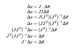
Similar to Option 4, but use the pseudoinverse of the Jacobian to compute a solution. For detail on the pseudoinverse, you may wish to look at these slides, but be aware they present the wrong pseudoinverse for our needs! We want this one:
If you choose to do this method, you may want to use the safe matrix inversion code in this archive to help avoid singularities: asst2.zip. You can also wish to explore the use of the damped least squares solution, as discussed in this paper and in class.
As with other options, if you choose to implement your IK technique in the provided motion capture viewer, you can find some documentation of the viewer at the bottom of this file. Sample skeleton and motion files can be found at the CMU database. You may start with this ASF file as the skeleton file and this AMC file as the motion file, as in Option 4.
Option 6. Skinning.
Skin several very different characters to the same skeleton using an existing system. Run the characters through some common motions (e.g., a walk cycle) and some extreme motions and evaluate the skinning result.
You may use Maya, an animation tool of your choice, or research software such as Pinocchio.
If you choose to explore Pinocchio, you may find that you cannot load your own motion easily into their system, but must use the motion provided with their demo software. Those sample motions are fine for this miniProject.
This website contains format conversions of the CMU motion capture database that are friendly for programs such as Maya, 3DStudioMax, and MotionBuilder, in case you wish to use those tools.
Deliverables and Handing in.
Your handin directory will be at
/afs/cs.cmu.edu/academic/class/15464-s15-users/andrewid if you are in 15-464 or
/afs/cs.cmu.edu/academic/class/15664-s15-users/andrewid if you are in 15-664.
You should provide:
- A README file describing briefly what you did and what you have uploaded into this directory.
- Your code and documentation of how to run it.
- Any source files required to run your code.
- Videos of animations demonstrating your system
- A 10-minute presentation: Submit your slides or website to describe your goals, techniques you used, as well as your results.
You will be randomly selected to demo/discuss 1 of your 2 miniProjects in class during the semester.
The Motion Capture Viewer.
Getting and compiling the code:
If you want to use the amc viewer code as your starter code,
you can get it here:
AMCViewer.zip
Windows:
Use the Visual Studio 2010 solution file provided in the ide/VS2010 directory. All the dependencies should be provided with the project zip file.
OSX:
You need to have the SDL library installed. There are two
ways to install SDL if you don't have it.
1. Install homebrew by following directions on http://mxcl.github.com/homebrew/
and type "brew install sdl" in the terminal.
2. Download it from http://www.libsdl.org
and install it manually.
Then the code can be compiled using ftjam, which can also be done in two ways:
1. If you installed homebrew, "brew install ftjam". You do not need
to copy anything in this case.
2. Download the source code from http://sourceforge.net/projects/freetype/files/ftjam/2.5.2/ftjam-2.5.2.tar.gz/download.
Extract it, run "make" from the terminal inside the directory, then
copy bin.unix/jam into the project's top-level directory.
Finally, run "jam" or "./jam"
inside the top-level project directory to compile the code.
Linux:
This code can be compiled using ftjam, which is available
from:
http://sourceforge.net/projects/freetype/files/ftjam/2.5.2/ftjam-2.5.2-linux-i386-glibc6.tar.gz/download
Extract it and put it in your project's top-level directory, then run "./jam" to compile the code.
If you are running the code from afs, and it does not link the first time, you
may need to change your ld path variable:
"% export LD_LIBRARY_PATH=$LD_LIBRARY_PATH:/usr/local/lib64".
Running the code:
By default, the the viewer expects
a "Skeleton.ASF" file with the AMC file in the "dist/data"
directory, but you can specify a different path if you like.
A simple camera control is provided. Use the left mouse button to rotate,
middle mouse button to zoom in/out, and the right mouse button to pan the
camera.
Space bar can be used to Play/Play in slow motion/Pause. Tab key can be used to
toggle the camera movement.
Using the code:
The base code has a lot of files to search through. Here is a list of the files and functions you're likely to find useful.
Library/Library.hpp
void Motion::get_angles(unsigned int frame, Character::Angles &into)
const; void Motion::get_pose(unsigned int frame, Character::Pose &into) const;
I recommend adding set angles (described below) if you plan to use Motion a lot.
Character/Character.hpp
void Pose::to_angles(Angles &into) const;
void Angles::to_pose(Pose &into) const;
Character/pose_utils.hpp
void get_world_bones(Pose const &pose, WorldBones &out);
The sections below describe these data structures and functions with a little bit of detail, organized by things you may wish to do.
Reading files and obtaining Motions
===============
#include <Library/Library.hpp>
#include <Character/Character.hpp>
Library::init("my/data/folder");
for (unsigned int idx = 0; idx < Library::motion_count(); ++idx) {
Library::Motion const &m =
Library::motion(idx);
for (unsigned int f = 0; f < m.frames(); ++f) {
Character::Pose
my_pose;
m.get_pose(f, my_pose);
}
}
The function Library::init Scans the given directory for amc/afs files and loads them.
You can retrieve these loaded files by calling
Library::motion(index) with 0 <= index <= Library::motion_count() .
Before we move on, here is a little bit more information about the Motion data structure.
The heart of a Motion is the "data" field. "data" is a list of joint angles for each frame of an animation.
The first N values are the joint angles for frame 0, the next N values are frame 1, etc. (Here N is the number of Degrees of Freedom in the skeleton)
The base code mainly treats motions as read-only, but if you plan to edit motions a lot, you may find this useful:
void Motion::set_angles(unsigned int frame, Character::Angles angles) {
assert(frame < frames());
assert(skeleton == angles.skeleton);
for(unsigned int i=0; i<data.size(), i++) {
data[frame * skeleton->frame_size + i] = angles.angles[i];
}
}
Angles
---------
Angles are raw joint-angle data, or basically what you would get if you just read the amc file yourself.
Angles is a rather tricky representation. It is effectively a list of joint angles, with one caveat: the first 3 values are actually the root x y and z position. After that, the next 3 values are the XYZ root rotation, followed by the XYZ rotation of bone 1, etc. These are Euler angle rotations, and to some extent, each rotation can be treated separately.
root_x = angles[0]; //position
root_y = angles[1]; //position
root_z = angles[2]; //position
root_X = angles[3]; //rotation
root_Y = angles[4]; //rotation
root_Z = angles[5]; //rotation
left_hip_X = angles[6]; //local rotation
left_hip_Y = angles[7]; //local rotation
left_hip_Z = angles[8]; //local rotation ...
Pose
============
A pose can be obtained from a Motion, and functions are available to convert between Angles and Pose
You can get a pose from a motion by calling:
m.get_pose(20, my_pose); //get pose at frame 20 into
my_pose
m.get_local_pose(20, my_local_pose); //get pose -- without root translation --
into my_local_pose.
Here are the conversion calls between Angles and Pose:
#include <Character/Character.hpp>
Character::Angles angles;
my_pose.to_angles(angles);
//...modify angles...
angles.to_pose(my_pose);
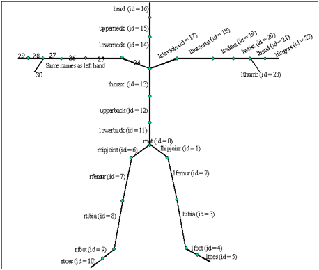
Pose consists of: a root position, a root orientation, and a list of orientations (quaternions) for the other bones. To find the orientation of a particular bone (other than root joint), you'll need to know its index is in the list. (This goes for WorldBones as well). The list of bones and their corresponding id's are as follows:
lhipjoint (id=0)
lfemur (id=1)
ltibia (id=2)
lfoot (id=3)
ltoes (id=4)
lowerback (id=5)
upperback (id=6)
thorax (id=7)
lclavicle (id=8)
lhumerus (id=9)
lradius (id=10)
lwrist (id=11)
lhand (id=12)
lfingers (id=13)
lthumb (id=14)
lowerneck (id=15)
upperneck (id=16)
head (id=17)
rclavicle (id=18)
rhumerus (id=19)
rradius (id=20)
rwrist (id=21)
rhand (id=22)
rfingers (id=23)
rthumb (id=24)
rhipjoint (id=25)
rfemur (id=26)
rtibia (id=27)
rfoot (id=28)
rtoes (id=29)
The figure below shows where all of these bones are.
The following shows how you may manipulate a pose:
Quatf quat;
quat = my_pose.bone_orientations[16]; //Get orientation of left shoulder //Compute new rotation.
...
my_pose.bone_orientations[16] = quat; //Set new rotation for left shoulder
Some quick notes on using quaternions in this codebase:
- All rotations are represented by quaternions
- Make a
quaternion by calling "rotation"
-between 2 vectors
-a rotation axis and an angle (in radians) - Apply a rotation by calling "rotate"
- Useful
properties to know:
-multiplying 2 quaternions composes the rotations one after the other
-conjugation changes the direction of rotation (so -q works as expected)
-quaternion multiplication is NOT commutative
Poses can be transformed into two other representations, Angles (as shown above) and WorldBones (as shown next).
WorldBones
------------
#include <Character/pose_utils.hpp>
Character::WorldBones wb;
get_world_bones(my_pose, wb);
//... do something with wb
//NOTE: no function to convert back.
WorldBones give you the absolute position of the base and tip of each bone along with the orientation of the bone's coordinate frame. This means you can think about bones without worrying about transforming them by their parents.
Displaying
============
#include <Character/Draw.hpp>
State no_state;
no_state.clear();
Character::draw(my_pose, no_state)
The draw function draws a pose at a given state (== additional absolute position + orientation for root bone). It gives a basic stovepipe-y character.
Writing
============
#include
<Library/WriteAsfAmc.hpp>
#include <fstream>
Library::Motion m =
Library::motion(idx);
Character::Angles angles;
std::ofstream outAMC("test.amc");
Library::writeHeaderAmc(outAMC);
for(int i=0; i < m.frames(); i++){
m.get_angles(i,angles);
angles.angles[0] /= m.skeleton->length;
angles.angles[1] /= m.skeleton->length;
angles.angles[2] /= m.skeleton->length;
Library::writeFrameAmc(outAMC,i,angles);
}
outAMC.close();
Note that we need to divide out the first three angles by the scaling factor. This is because the first three angles are actually translations in the root joint, which do get affected by the scaling factor.
Motion Capture File Format:
The code base will read and display motion-captured data for you, but understanding the file format (.asf and .amc) is still very useful. The world coordinate system is Y up. The skeleton file (.asf) describes how the bones are connected, their degrees of freedom, their local coordinate system, etc. while the motion file (.amc) describes each bone's rotation angles relative to the bone's local coordinate system at each time step.
In an ASF file, each bone is described as following:
begin
id bone_id
//Unique id for each bone
name bone_name
//Unique name for each bone
direction dX dY dZ
//Vector describing direction of the bone
//in world coordinate system
length 7.01722
//Length
of the bone
axis 0 0 20 XYZ
//Rotation
of local coordinate system for
//this
bone relative to the world coordinate
//system.
In .AMC file the rotation angles
//for
this bone for each time frame will be
//defined
relative to this local coordinate
//system
dof rx ry rz
//Degrees
of freedom for this bone.
limits (-160.0 20.0) (-70.0 70.0) (-60.0 70.0)
end
The parent-child relationship of the skeleton is defined in
the ":hierarchy" section of the ASF file.
Each line lists the parent, and then its children. For example:
"root lhipjoint rhipjoint lowerback"
Root is a parent and lhipjoint, rhipjoint, lowerback are
root's children.
The following picture shows the skeleton hierarchy defined in ASF file.
Interactivity:
If you wish to make your system interactive, the best place to add interactivity in the provided viewer is in Browser/BrowseMode.cpp. There is already an SDL event handler set up (namely "handle_event"). More thorough documentation of SDL can be found at http://www.libsdl.org/docs/html/eventfunctions.html.
Video Recording:
Videos can be implemented in several ways. You can use the frame dumper (FrameDumper.hpp, FrameDumper.cpp in "Graphics" directory) in the code base by adding a hotkey to your program. These frames can be coalesced into a movie using software packages (ImageMagick and ffmpeg on Linux, Quicktime Pro on Mac, and VirtualDub on Windows). You can also use screen capture programs to record your videos.
Further notes related
to building a Jacobian:
Here are some more notes specific to computing the Jacobian with the motion capture viewer, with answers to common questions.
Flow for numerical
jacobian – successively modify the correct angles and look at how the end
effector position has changed.
(1) How do we get at the joint angles?
In Library/Skeleton.cpp, take a look at:
void Skeleton::build_pose(double const *frame_data, Character::Pose &pose)
notice the use of get_dof_rot
get_dof_rot(bones[b].dof, frame_data, bones[b].frame_offset);
every bone b has a start position and a number of degrees of freedom in the Angles array .. from get_dof_rot:
Quatd get_dof_rot(string const &dof, double const *info, int start_pos) {
info += start_pos;
for (unsigned int i = 0; i != dof.size(); ++i) {
double d = *info;
// do something with angle d
++info;
}
}
We can modify this angle data structure directly, angle by angle, as long as we also modify it back when we’re done.
The set_angles method already mentioned above can be used to change angles all in one shot if we really know what we are doing with the angles array.
void Motion::set_angles(unsigned int frame, Character::Angles angles)
{
assert(frame < frames());
assert(skeleton == angles.skeleton);
for(unsigned int i=0; i<data.size(), i++)
{
data[frame * skeleton->frame_size + i] = angles.angles[i];
}
}
(2) How do we compute a new pose after changing the joint angles?
convert angles to a Pose object using:
void Angles::to_pose(Pose &pose) const;
you can also draw the character .. I’d suggest starting with setting large angle changes and drawing the result to see if you’re getting things right for debugging purposes
Character::draw(pose, <other stuff>);
(3) How do we get motion of the end effector?
convert Pose to WorldBones using:
get_world_bones(pose, world_bones);
bone tip position information is available from the WorldBones data structure
Flow for analytical jacobian
– we must find the axis and lever arm in the world coordinate frame
(4) How do we get the lever arm?
This can come directly from the WorldBones data structure and should already be in world coordinates
(5) How do we get the rotation axis in world coordinates?
Step 1. Get the axis numerically. Supply a change in joint angle and take the cross product (tipPos-jointPos) from before and after. These values should be available from WorldBones
Step2. Understand the code in put_dof_rot and essentially invert it.
One more possibility: treat all bones as if they are 3DOF, compute the desired quaternion rotation, and push it down to the joint angles using put_dof_rot. Or .. forget about angles altogether and just start drawing the computed pose .. joints may appear to “break.”
We could treat all
joints as if they are 3DOF joints, solve the system, and project back down to
angles. However, this does not give
us a solution that minimizes motion along DoF that are actually available to the
character and will not produce a correct result.
What
to know about quaternions.
Basic representation
Composing quaternions
Rotating a vector using a quaternion representation
Converting an angular velocity integrated over some timestep into a quaternion.
Other handy conversions