Getting started with the MWB demo
The basics
MWB has a full undo/redo stack and file load/save capability. It supports a number of different simulators, which can be selected between using Simulate → Simulator:
- Open Dynamics Engine, developed by Russell Smith.
- Bullet Physics Library
- Ageia PhysX SDK. To use this, you need to have the drivers installed on your system, which can be found here; otherwise it will be disabled.
Modes
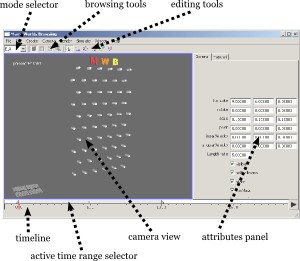
Major components of the MWB window.
The application has two basic modes of operation: Edit
and
Browse
. Switch between these modes using the mode selector in
the upper-left-hand corner of the window.
Edit mode is for any sort of initial scene setup: creating simulation objects, moving them around, etc. During the browsing process you can always switch back to edit mode if you need to change initial state, create new objects, etc. While in edit mode, you can additionally preview the simulation without having to enter browsing mode using Simulate → Run Simulation.
Browse mode is where all of the Many-Worlds Browsing happens: new simulation paths are computed and displayed, and you can browse, select, and refine them.
Camera controls
The keyboard and mouse controls were modeled after Autodesk Maya, since this is what I am most familiar with. To move the camera around, hold down the Alt key. The left button rotates, middle button pans, and right button dollies the camera. Note that in this particular setup, the up vector (y) is always fixed, which makes sense here since this is also the direction of gravity.
In the initial setup, you have 4 scene cameras. Switch between the 4-view mode and the 1-view mode by pressing the spacebar. You can change the camera for the currently selected view using the Camera menu. To create a new camera (should this be necessary), use the Create menu.
Edit mode
The first step in the process is to actually set up your scene, including the various objects that will be in it and their initial state. This process is performed in Edit mode, which you will return to later if you need to add aditional objects or other scene modifications during the browsing process.
Editing tools. From left: Select, Translate, Rotate, Scale, Move pivot, Select vertices.
Objects once created can be manipulated through two major means: firstly,
position, rotate, and scale can be manipulated through the various
editing tools. Select among the various modes (select, translate, rotate,
scale) using the toolbar buttons, or use the shortcut keys q
, w
,
e
, and r
. The other major mode of interaction is to edit
Attributes, which are listed in the attributes panel. When in
edit mode, display the attributes panel with Ctrl-A or through
Window → Attributes.
Collision objects
The application supports a number of different collision primitives. Not all objects are supported by all simulators, however. Table 1 shows which simulator choices support which collision primitives. Collision objects are created through the Create menu and can be moved, rotated, and scaled into place through the various edit tools.
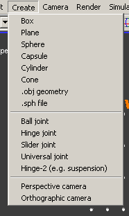
Creating objects through the Create menu.
Notes on specific collision objects:
- Cylinder
- To change the length of the cylinder, edit the
Length ratio
attribute. - Capsule
- A cylinder with spheres at the ends. Like the cylinder,
you can change the length by editing the
Length ratio
attribute. - .obj geometry
- Arbitrary .obj meshes can only be simulated if
they can be decomposed into convex regions. Automated convex decomposition is
available by selecting the object and using Edit → Fit Convex
Hulls. To fit hulls by hand, go into vertex selection mode (using the
toolbar button) and select a set of vertices. Edit → Create convex
hull from points will then generate a hull from the selected points. Note
also that the mass calculation only works for closed objects; if you need to
simulate meshes that are not closed you will need to turn off the
hasMass
attribute on the mesh and fuse if with some mass-containing proxy objects to generate a valid inertia matrix. - .sph file
- MWB supports
.sphfiles generated by Gareth Bradshaw's Sphere-Tree Construction Toolkit, which are simply converted to spheres for the purpose of simulation.
| Box | Plane | Sphere | Capsule | Cylinder | Cone | Convex hulls | |
|---|---|---|---|---|---|---|---|
| Open Dynamics Engine (native CD) | • | • | • | • | • | ||
| Open Dynamics Engine (Bullet CD) | • | • | • | • | • | • | |
| Bullet Physics Library | • | • | • | • | • | • | |
| Ageia PhysX API | • | • | • | • | • |
Table 1: Supported objects for the 4 available simulators in Many-Worlds Browsing.
Grouping objects
MWB is a fully hierarchical modeling system. All objects (including joints) can be grouped together and scaled/rotated/translated together. One major limitation is that most of the collision objects do not support shearing and in addition many do not support nonuniform scales. This means if such objects are grouped together they can only be scaled uniformly since nonuniform scaling and rotation can be combined to generate an arbitrary shear. This restriction is not enforced very robustly and can be overridden easily by hand-modifying the generated files, but I cannot predict what the results will be.
To group objects, use Edit → Group or press Ctrl-g. To visualize and manipulate the hierarchy, use the hierarchy view (Window → View Hierarchy); the middle mouse button can be used to drag objects around.
Fusing objects
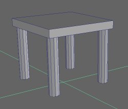
Fusing objects A nonconvex table created by fusing 4 cylinders and a box.
The provided collision primitives are all convex and mostly very simple. It does, however, support the generation of nonconvex objects using a union of convex objects. To generate such a union, select the objects and press Edit → Fuse.
Joints
MWB supports a number of different joint constraints. To create a joint constraint between two objects, select the two objects and select the appropriate joint in the Create menu. A visualization of the joint object is created at the origin, which can then be moved and rotated into place. Parameters such as the joint center and axes are determined by how the joint object is placed, but this should be fairly intuitive. A more complete description of the various joint types can be found in the Open Dynamics Engine documentation.
Randomizing state
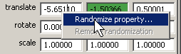
Randomizing properties by right-mouse-clicking in the attribute panel.
In order to vary initial positions, velocities, etc. during the sampling
process, use the randomization features present in the demo. Any float-valued
attribute can be randomized. To do this, simply click with the right mouse
button on any attribute in the attribute panel and select Randomize
property
in the context menu. It will ask you for a range of values;
during sampling, values are chosen uniformly from this range. To disable
randomization, select Remove randomization
from the same menu.
Browse mode
As soon as you switch to Browse mode, the software begins sampling different
simulation worlds. To visualize these paths, simply select an object in the
scene. Note that you have to select at the correct level in the hierarchy
(e.g., if you are simulating a box, it does not work to select the box's
parent). To make selection simpler, you can change the selection mode to
Simulated
through Edit → Select by → Simulated. There
are a few tools available to help sort through
the various possibilities.
Selection tools
Browsing tools. From left: Select path, Draw positive constraint, Draw negative constraint, Refine.
There are 3 major tools for selecting and modifying object paths.
- Positive constraint
- Restrict the search to paths that pass through the selected region. Applies only to selected objects. Some limitations of these constraints are described in the paper.
- Negative constraint
- Restrict the search to paths that do not pass through the selected region. Applies only to selected objects. Some limitations of these constraints are described in the paper.
- Refine paths
- Refine the paths of selected objects starting at the selected region. Details of this process can be found in the paper.
Simulation sorter
Sort through simulations ordered by various criteria in the Simulation sorter. This window can be accessed through Window → Simulation sorter, and the interface should hopefully be fairly intuitive.
Modifying the scene
To add/remove/change any object in the scene, go back to edit mode. Edited objects will be marked in red to indicate that their motion will need to be modified to get a physically accurate simulation. When you switch back to edit mode, however, it will still be sampling on the old scene; to correct this, choose Simulation → Update sample which will update the motion of all modified objects with newly computed physics.
Timeline
To visualize a particular simulation, you can either scrub across the timeline using the left mouse button or use the Play button. The standard camera controls also work in the timeline to expand/contract the region visualized.
To make sure simulations finish reasonably quickly, we restrict how long they are allowed to run. This is controlled through the active region, a small bar on top of the timeline. Drag the small handles on the ends of the active region to expand the active region. If you have a particular simulation the you like but which terminates too early, you can always select it and refine the tail end of the path, which will correct this.
Exporting the data
Once you are happy with a particular simulation, there are a variety of different methods for rendering/exporting the motion.
- .ma file
- A Maya Ascii format file for reading into Autodesk Maya.
- Image sequence
- An OpenGL-rendered image sequence.
- Timelapse image
- Renders the motion as a long-exposure photograph, like on the first page of the paper. The image is exported in OpenEXR format, which must then be converted to LDR using some external program.
|
|
|
Comments, questions to Christopher Twigg. We support web standards; this page is valid XHTML 1.0 Transitional and CSS.