
3d Photography on your desk
An implementation of Jean-Yves Bouguet and Pietro Perona's paper for my 15-463 final project.
Script usage:
The idea of Bouguet and Perona's 3d photography on your desk is to scan 3d objects using a single camera and a calibrated light source.
The 3d position of the camera relative to the ground plane is captured using Jean-Yves matlab calibration toolbox. This is used to calculate the position of the light source from the shadow images by creating two rays in space to the light source.
Once the light source and camera have been calibrated, then the scanning is done by waving a straight cylindrical object in front of the light source to cast a shadow onto the object and ground plane. It is important that the shadow cast into a known area of ground plane to later reconstruct the shadow plane in the camera space.
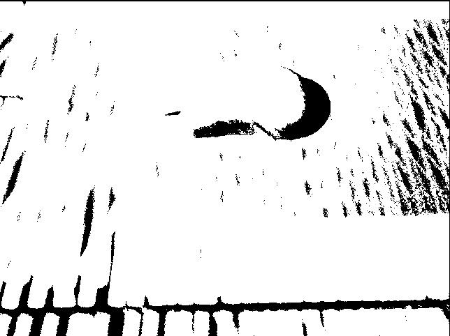
The first step is preprocessing the images to determine what areas are recoverable by calculating where there is enough contrast in intensity. Then a threshold value is determined by finding the mean of the min and max values for that pixel. The binary mask of if a pixel is recoverable is multiplied by the perpixel threshold value to come up with an image that determines if an area is shadowed by when the source pixel is darker than the one in this image.
The next step is to loop over the images and determine when each pixel was first seen by the shadow (presumably at the edge). When the pixel is first shadowed the time to sub frame accuracy is recorded by linearly interpolating the intensities of the current frame and the last frame to determine when the shadow edge hit the pixel. This makes the assumption that the velocity of the shadow in that local timeframe was constant and the shadow has a smooth interpolation across its boundary. In implementation it also implies that the object should be waved in a slow manner to have the shadow ramp up to the value across two frames.
After the sub frame accuracy image of when each pixel was first shadowed, the A and B points of the shadow on the ground plane are determined for that time by looking up where the shadow edge was at that particular time across a horizontal scan line on the top and bottom of the image that is always on the ground plane. Since the time value can be fractional, the frame before and after the subframe time are used to interpolate the A and B points.
With the A B and light source points and the knowledge that the object is a rod, we now know that the target pixel exists in the plane of A,B and the light source. The A and B points are determined in camera space by rotating and translating the ground plane into camera space and intersecting the ray through the image with the ground plane. With those two points and the Light source location a new plane can be formed, called the shadow plane. We then find the intersection of the ray through the image pixel with the shadow plane to get the 3d location of that pixel in camera space. At this point there is enough data to reconstruct the scene through the 3d points that are recovered from the image.
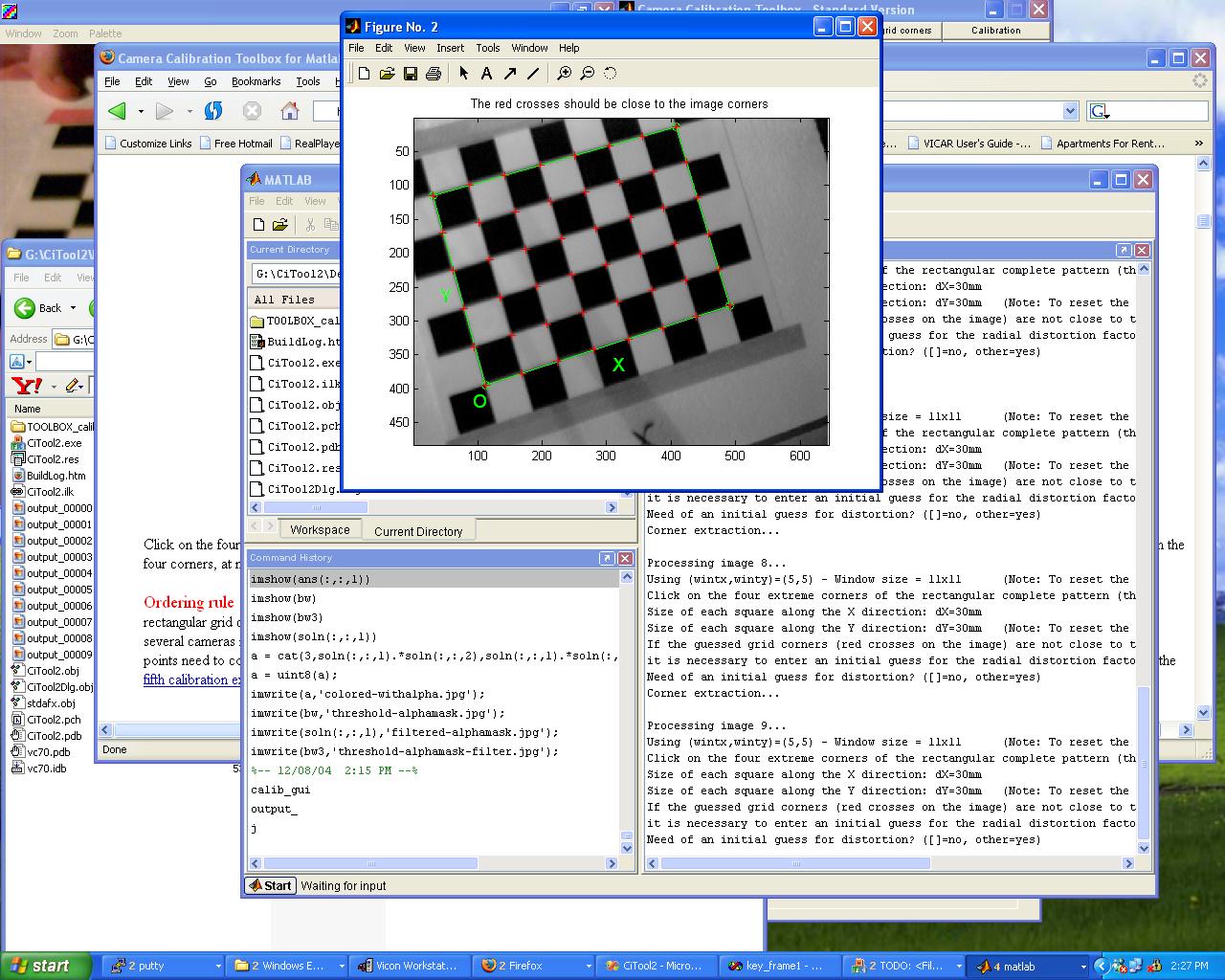
Camera calibration done with Camera Calibration toolbox for matlab. http://www.vision.caltech.edu/bouguetj/calib_doc/. Uses a variety of checkerboard poses to determine intrinsic and extrinsic parameters.

Light source calibration to triangulate the position of the light source in World space. Convert to camera space with Rc_1*pt1+Tc_1. Important points for the light calibration are that two points are known to be on the ground plane, the other is on a ray orthogonal to the ground plane, and starting at one of the known points.

Determine the contrast of a pixel. Keep Max and Min for each pixel over all images. For low contrast pixels, we can not determine when it is actually shadowed, so it should be ignored. For pixels with enough contrast, set the trigger for being shadowed as the mean of the min and max values of that pixel. This helps correct for the lack of a perfect point light source on different backgrounds.


Only the shadow edge is used determine points, but we can't put the shadow edge at every possible point we want to scan. The solution is to linearly interpolate the data.
What we want is to know for each pixel, where the shadow is on the image plane, where the light source is, and the ray from the camera, through the image. The 3d space plot of where the pixel is corresponds to the intersection of the ray through the image from the camera with the shadow plane for that specific point in time where the pixel is first shadowed. To do this we build an image of when each pixel is first shadowed. To find the exact time we do a linear approximation between the first frame when it is shadowed, and the the previous frame. We find out at what t the temporal brightness function (image-maskedmean) intersects the I=0 line (time-axis).
AlgorithmFor all images For all pixels if shadowed if firstshadow lineartimeapproximation
Once the timemap is made of when each pixel has first seen the shadow, we then look up where A and B linearly interpolate to at that frame. They will show where the shadow plane intersects with the ground plane (table).
AlgorithmFor all pixels t = pixeltime t0 = floor(t) t1 = ceil(t) A = LookupPt(HorizontalRef1,t0) A' = LookupPt(HorizontalRef1,t1) B = LookupPt(HorizontalRef2,t0) B' = LookupPt(HorizontalRef2,t1) alpha = mod(t,1) Amix = (1-alpha)*A' + alpha*A Bmix = (1-alpha)*B' + alpha*A plane = world2camera(Amix,Bmix,Ls) ray = normalize([x,y]',fc,cc,kc,alpha_c) % 3dpt in camera space. 3dpt = isect(ray,plane)
Output a depth image with the t's of the ray/plane intersections and display as a heightmap.