Matt Pucevich, 11/12/04
This program (FaceMorph) is designed to produce a smooth morph between two given images. It requires the user to define correlated control points between the two images. This program takes five arguments:
imAname: The name of Image A (as a string); the first image from which the morph will begin.
imBname: The name of Image B (as a string); the final image into which Image A will be morphed.
destnamebase: The base name under which to save the output frames. Image A will be saved as "[destbasename]00.tif", and the first morph frame will be saved as "[destbasename]01.tif", and so on.
nframes: The number of total frames in the morph. This number includes Image A and Image B. Thus setting nframes to 3 will result in the starting image, one generated morph frame in the middle, and the final target image.
npoints: The number of control points to be defined by the user between the starting and finishing images.
Example: FaceMorph("Matt.jpg", "Ben.jpg", "morph", 61, 40) will produce 61 images, numbered morph00.tif to morph60.tif, where morph00.tif is the starting image (Matt.jpg), morph60.tif is the finishing image (Ben.jpg), and morph01.tif through morph59.tif are generated transition frames between them. The program will request 40 control points from the user before crunching out the frames.
The generation of the face warp is broken down into four main phases (Phases two through four are repeated for every generated frame):
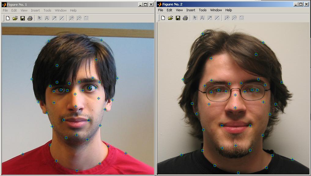
Phase 1: Aquire correlation points (control points) The first step in the process is to find out exactly how the two images fit together. To do this the user is prompted to define pairs of points on each image which are the same, by clicking a spot on the first image, then clicking on the second image where that same place falls. This process is done until numcorrpts have been defined.
Defining correlation points:
Phase 2: Triangulate images and recover transformations The second step in the process is to break the two endpoint images into triangles using the defined control points as verticies (known as triangulation), and then observe the differences between either endpoint's triangles and the triangles of the current morph frame under calculation. The endpoint images are triangulated by a call to delaunay() (Node: This occurs before execution enters the main loop over all generated frames to save computation).
The location of the control point in any given frame is computed as a smooth interpolation between their location in the starting image to their location in the final image. Then, once the locations of all control points in the current frame under computation is known, 2 calls to cp2tform() are made. These calls compute, for every triangle of either endpoint image, the transformation necessary to move the triangle in an endpoint image into its position in the current morph frame under computation. The two separate calls to cp2tform compute the transformations from the starting image to the current frame, and the ending image to the current frame.
Step 3:Compute the corresponding points of source images with the current frame's pixel grid The third step is to figure out to where all of the pixels in the current frame under computation map. First, 2 calls to tsearch are made. The first call computes in which triangle of the starting image each pixel of the current frame lies, and the second call computes in which triangle of the target image each pixel of the current frame lies (the starting and finishing image need not have the same triangulation). Once it is known in which triangle a given pixel of the current frame lies, we know how that pixel has transformed from either source image. Now, the specific coordinate to which all of the current frame's pixels map in either endpoint image is calculated. For every pixel, the inverse transformation from its location in the current frame to its location in each source image is calculated.
Phase 4: Fill in color values, blending from both images to current frame The final step, now that it is known where all of the pixels in the current frame get their color (the cooresponding coordinates in either endpoint image), calls to interp2 are made, given the coordinates in the endpoint images, to compute the actual color value of every pixel in the current frame from the starting image and from the final image, and finally the contribution from each endpoint image is scaled according to where the current frame lies in the transition from start to finish.
Thanks to Ben Hollis (my image target) for helping me generate the nifty flash animation to show off my results: